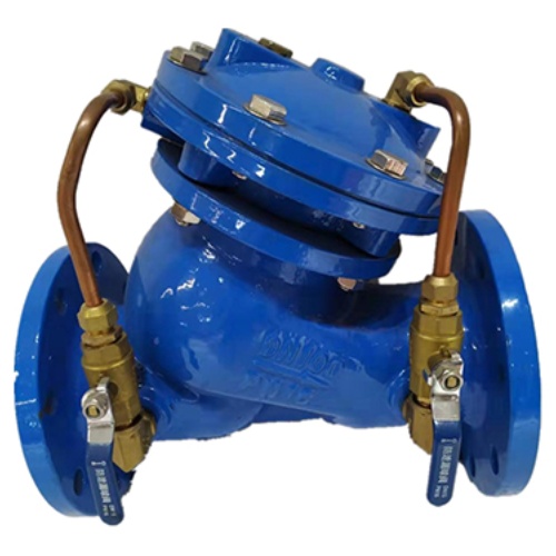

Control Valve
Power equipment for conveying Multi-functional pump control valves combines three valve types in one system: gate valves, check valves, and water hammer eliminators. Each valve type plays a specific role in pump operation, ensuring proper flow control and protection.
Product Description
A multifunctional pump control valve comprises a main valve, a regulating valve, and a receiver system. The valve body uses a DC-type valve body. The main valve control chamber is a diaphragm-type or piston-type double-control-chamber design. Compared with a standard hydraulic control valve, the control chamber is extended by one additional chamber, which enhances the main valve’s control capability and enables multifunctional pump outlet control, including slow opening, full opening, slow closing, and stopping. This provides multifunctional control of the pump outlet using a single valve and a single adjustment—offering true multifunctional control.
This product is used in high-rise building water supply systems and other water supply pump outlet pipelines. It helps prevent and attenuate water hammer caused by pump start-up and shut-down, prevents backflow to protect the pump, and maintains pipeline safety. To enable automated pump operation, simplify management, reduce labor, and improve reliability, hydraulic and electric valves have been adopted to replace manual valves. Continuous technical improvements have been applied to monoblock valves, and a range of new valve types have emerged, including slow-opening and slow-closing backstop valves, slow-acting open/close hydraulic valves, automatic slow-closing gate valves, and double-speed self-closing valves. For more valve types, please refer to the valve series.
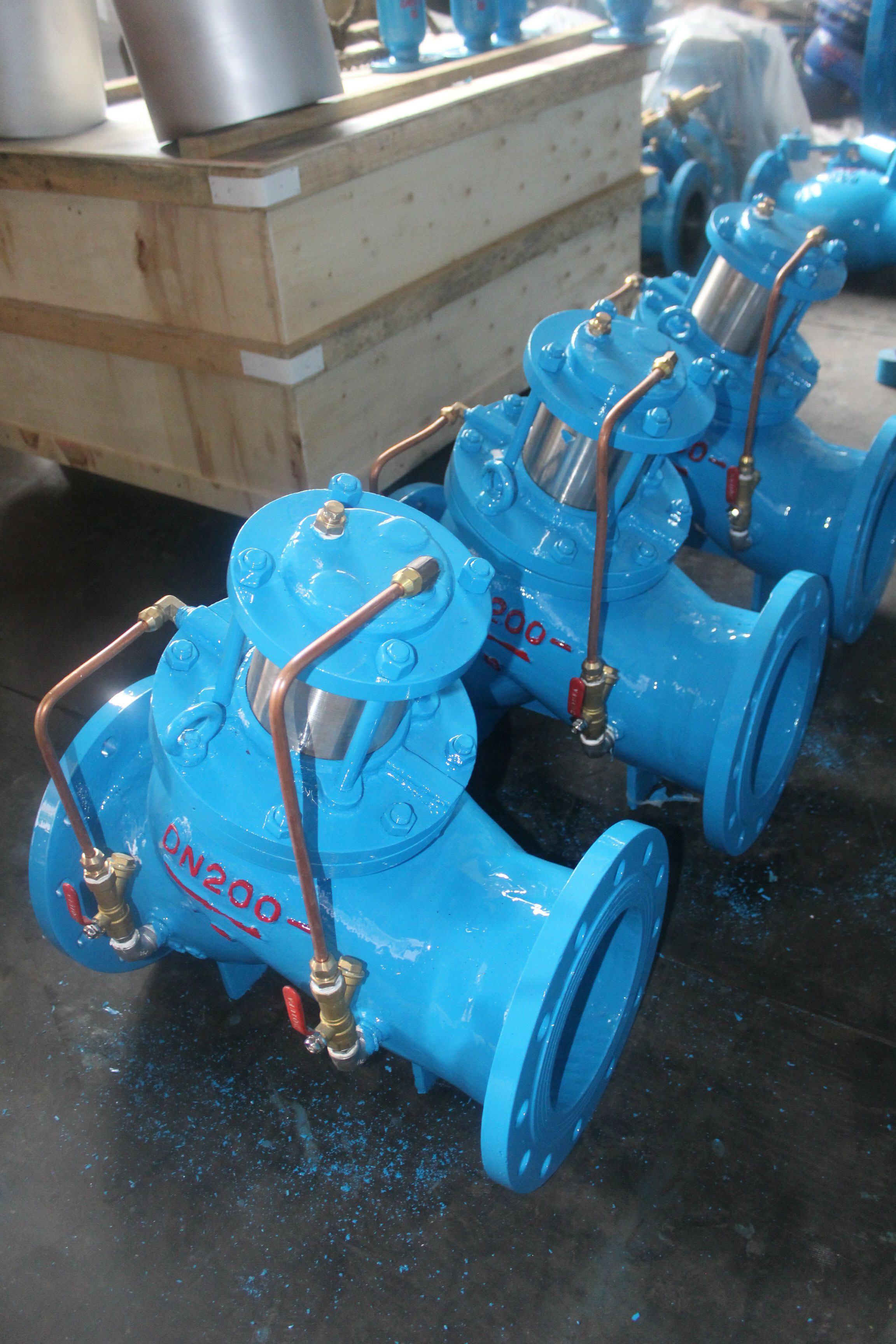
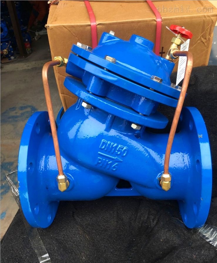
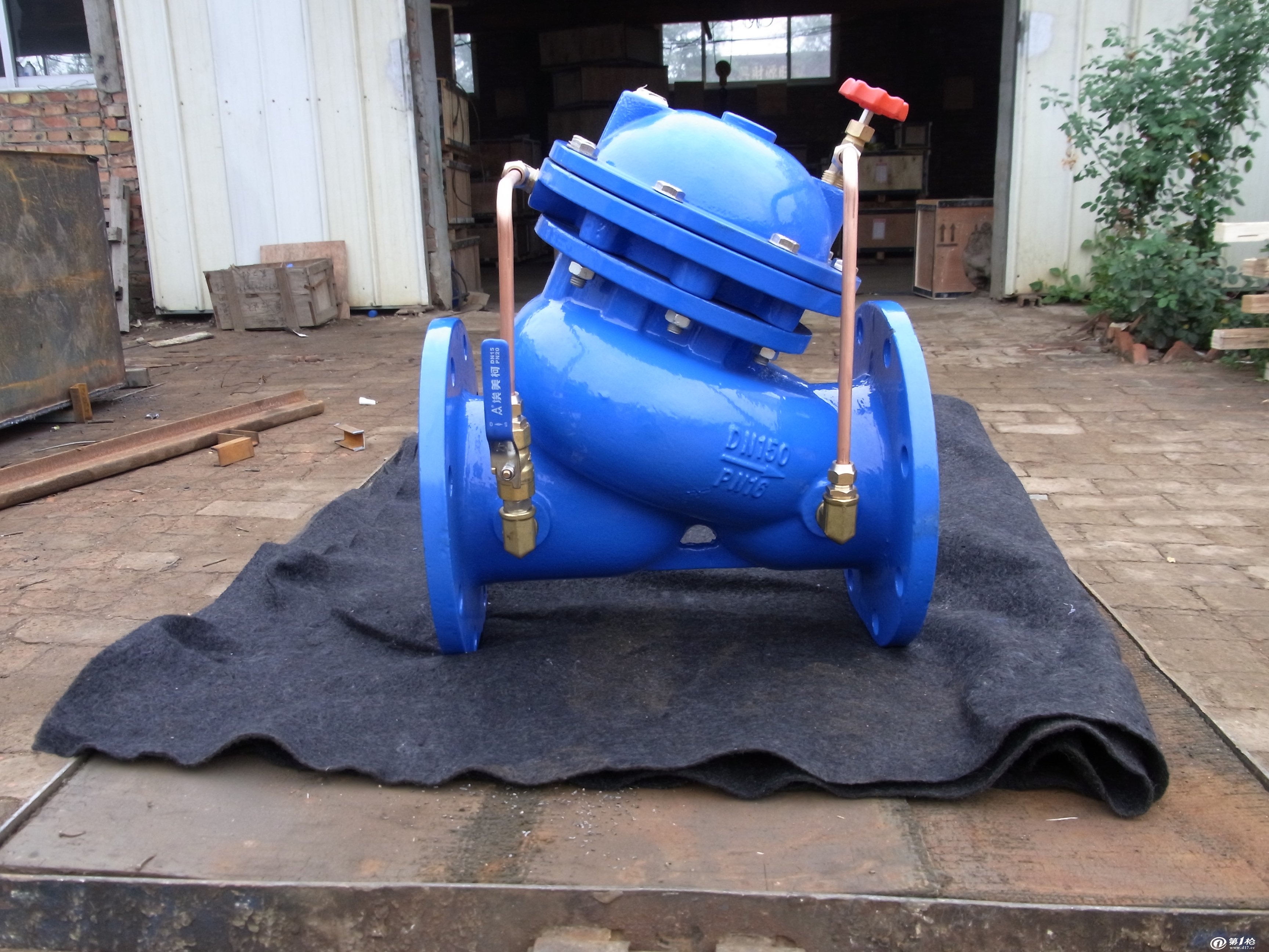
Product Detail Drawing
Product Basic Functions
Gate Valve
The gate valve is usually kept in the closed position. When the pump starts, the gate valve is opened slowly. When the pump is stopped, the gate valve closes quickly first, and then closes slowly after reaching a certain degree of closure. This closed-gate start and closed-gate stopping sequence can effectively prevent water hammer during pump start-up and shut-down. At the same time, it reduces motor load at pump start-up; at the minimum shaft power flow point, the flow rate is generally about 30% of the design shaft power. Another function of the gate valve is that, when closed, it provides safe isolation conditions for backstop valves and pumps installed between the gate valve and the pump, helping prevent backflow from the pressure pipe.
Check Valve
The check valve prevents the water flow from reversing direction due to sudden power failure and thereby prevents backflow. Sudden pump shutdown can easily cause water hammer. When the pump’s static head is high, the instantaneous high pressure associated with severe water hammer may lead to pipe rupture and serious production accidents.
Water Hammer Eliminator
A water hammer eliminator can effectively eliminate various types of fluid surges in a transmission system. It does so without requiring the flow to be stopped, even when irregular water hammer and surges occur. This reduces destructive shock waves and provides a protective function. Therefore, to prevent water hammer damage on transmission pipelines, a water hammer eliminator is often installed on pump pressure water pipelines.
Three-in-One Protection: How Multifunctional Control Valves Integrate Gate, Check, and Water Hammer Eliminator Functions
STORAEN’s control valve redefines industrial fluid management by combining three critical functions—gate valve isolation, check valve backflow prevention, and water hammer elimination—into one compact design. Engineered to replace traditional multi-valve arrangements, our flow control valve and water pressure control valve solutions simplify pipeline systems while improving safety and operational efficiency. They are ideal for high-rise water supply applications, industrial pumping stations, and utility networks.
1. Integrated Gate Valve: Precise Flow Isolation
At the core of this multifunctional control valve is a heavy-duty gate valve mechanism, providing reliable on/off control for maintenance or emergency shutdowns:
Full-Bore Passage: A parallel gate design (DN50–DN1400) ensures minimal pressure loss (≤0.01MPa) and unrestricted flow when fully open, delivering improved energy efficiency (reference: up to 20%) compared with conventional gate valves.
Dual-Seat Sealing: Soft rubber or metal-to-metal seals (depending on the media) achieve bubble-tight shutoff, which is critical for isolating pumps or pipelines during repairs without residual-flow risk.
2. Built-In Check Valve: Automatic Backflow Protection
Eliminating the need for a separate check valve, the design uses a spring-loaded disc that closes instantly when flow reverses, protecting pumps from damaging backflow:
Low-Crack Pressure Design: The disc opens at just 0.05MPa, ensuring smooth forward flow in low-pressure systems, while shutting within 0.2 seconds of flow reversal (reference: faster than standalone check valves by 30%).
Particle Resistance: A streamlined valve body reduces debris accumulation, making it suitable for water containing small solids (e.g., sand or scale) without compromising sealing performance.
3. Advanced Water Hammer Eliminator: Controlled Closure Technology
The third integrated function addresses the “silent killer” of pipelines—water hammer—using a dual-control-chamber system:
Slow-Shut Mechanism: A diaphragm or piston-type control chamber (user-selectable pressure-control-valve types) adjusts closure time from 3–120 seconds, suppressing water hammer peaks to ≤1.5× working pressure (reference: versus 3× in traditional setups).
Three-Stage Operation:
Fast Closure of the Main Disc (80% stroke in 5s) to stop high-velocity flow;
Gradual Closure of the Pilot Valve (remaining 20% over 30–120s) to eliminate pressure surges;
Automatic locking in the closed position to prevent backflow during pump shutdowns.
Tailored to Your Fluid Control Needs
Whether managing a high-rise water distribution network or an industrial cooling system, our water control valve and flow control valve types deliver exceptional versatility. The integrated design not only simplifies maintenance but also enhances system reliability by eliminating failure points between separate valves.
Upgrade to STORAEN’s control valve solution and experience the advantages of three critical functions in one robust package—engineered to protect your pipelines, extend pump service life, and streamline operations. Explore our pressure control valve types today and discover why smarter fluid management starts with integrated innovation.
Diaphragm vs Piston Control Chambers: Core Technologies for Pressure Regulation in Multifunctional Valves
In STORAEN’s control valve designs, choosing between diaphragm and piston-type control chambers is critical for achieving precise pressure regulation and stable flow control. As two primary pressure-control-valve technologies, each offers distinct advantages tailored to specific industrial requirements—here is how they work and where each performs best.
1. Diaphragm Control Chambers: Smooth, Low-Noise Regulation for Clean Media
Ideal for water supply, HVAC, and low-particle systems, diaphragm chambers use a flexible EPDM or NBR membrane to convert pressure into controlled motion:
Operation Principle: Upstream pressure acts on the diaphragm, pushing it downward to adjust the valve disc position. A return spring balances the force, enabling stepless flow modulation with minimal hysteresis (≤1.5% of full scale).
Key Benefits:
Cost-Effective & Leak-Proof: No mechanical seals or moving parts exposed to the media, which reduces maintenance by 20% and eliminates contamination risks in potable water or pharmaceutical lines.
Quiet Operation: The soft membrane absorbs vibration, making it suitable for noise-sensitive environments such as high-rise buildings (reference: noise ≤65 dB during operation).
Limitations & Reference Parameters: Best suited for pressures up to 6.3MPa and temperatures -10°C–80°C; not recommended for abrasive fluids. Commonly used in STORAEN’s water pressure control valve and flow control valve models for municipal applications.
2. Piston Control Chambers: Heavy-Duty Performance for High-Pressure, Harsh Media
For industrial processes involving high pressure, high temperatures, or particle-laden fluids (e.g., wastewater and oil), piston chambers provide robust mechanical control:
Operation Principle: A cylindrical piston (cast iron or 316L stainless steel) converts hydraulic or pneumatic pressure into linear motion, directly actuating the valve stem with high torque (up to 500 N·m).
Key Benefits:
Extreme Pressure Resistance: Handles up to 10.0MPa and temperatures up to 150°C, providing reference performance advantages over diaphragms by 60% in high-pressure scenarios such as industrial boiler systems.
Abrasion Tolerance: A hard-chrome-plated piston surface resists scratches from sand, scale, or sludge, ensuring a reference cycle life of 50,000+ cycles in abrasive environments—critical for mining or chemical plants.
Design Notes: A double-directional mechanism prevents lateral movement, minimizing seat wear and maintaining sealing accuracy (reference: leakage ≤0.01% of rated flow).
When to Choose Diaphragm vs Piston?
Media Type: Diaphragm for clean liquids/gases; piston for dirty fluids, high-viscosity media (e.g., lubricating oil), or steam.
Control Precision: Diaphragm provides finer adjustment (reference: 0.5% resolution); piston prioritizes power and durability.
Industry Fit:
Diaphragm: Water distribution and building automation (water control valve applications).
Piston: Petrochemical, power generation, and heavy industry (paired with our flow control valve types for process pipelines).
STORAEN’s Engineered Excellence
Customization Options: Both designs comply with control valve sizing standards (ISO 5208, GB/T 17213), with configurable stroke lengths (25–300mm) and feedback sensors (4–20mA) for automated systems.
Reliability Upgrades: Diaphragms feature anti-tear aramid reinforcements; pistons include self-lubricating PTFE rings, reducing friction by 30% compared with generic models.
Make the Right Choice for Your System
Whether you need the precision of a diaphragm chamber or the ruggedness of a piston chamber, STORAEN’s control valve solutions deliver optimal pressure regulation for your specific operating conditions. By understanding these core technologies, you can select the appropriate pressure-control valve type to improve efficiency, reduce downtime, and meet even the most demanding industrial requirements. Contact us today to learn how our engineering expertise can elevate your fluid control system.
Principles of Construction
Working Principle
(1) When the pump is stopped, the valve plate closes at the outlet end, and the upper diaphragm chamber is closed under static pressure.
(2) When the pump starts, water pressure is transmitted into the lower chamber via the bypass pipe. The main valve plate and the slow-closing valve plate then open slowly under the inlet-end and lower-chamber water pressure.
(3) Under the inlet-end pressure, the valve plate rises to the maximum opening state. The opening height is determined by the flow rate.
(4) Immediately when the pump stops, the flow rate and pressure drop suddenly, and the main valve plate begins to move downward under the action of gravity.
(5) When the flow rate is close to zero, the main valve closes. The main valve plate remains partially on the relief holes to weaken the impact of water hammer. Meanwhile, the pressure difference between the lower and upper cavities causes the valve outlet water pressure to be introduced from the bypass pipe into the upper cavity, promoting diaphragm pressure. As a result, water discharged from the lower cavity into the valve inlet causes the slow-closing valve plate to begin slowing its closure.
(6) The slow-closing valve plate fully closes the drain hole, and the valve returns to the initial state of the pump.
Basic structure
The overall size of the valve is comparable to that of a conventional check valve and consists of the main valve and external accessories. The main valve includes the valve body, pressure plate and diaphragm, large valve plate, slow-closing valve plate, valve seat, stem assembly, and other components. The slow-closing valve plate is connected to the pressure plate and diaphragm via the stem assembly. The diaphragm is clamped between the valve cover and the diaphragm seat, and the up-and-down movement of the diaphragm drives the slow-closing valve plate up and down.
The valve stem passes through the central hole of the large valve plate, allowing the large valve plate to slide along the valve stem within a certain range. Normally, the large valve plate is pressed against the valve seat by its own weight, keeping the valve in the closed state. Multifunctional pump control valve external accessories are installed on both sides of the diaphragm and on the inlet and outlet pipe. The diaphragm’s lower chamber and the connecting pipe on the valve inlet side are equipped with control valves, filters, and a special backstop valve.
The diaphragm upper cavity and the valve on the outlet side of the connecting pipe are equipped with a filter and a control valve only. The movement and position of the large valve plate and the slow-closing valve plate within the main valve determine changes in the valve’s operating state and opening/closing behavior. The external accessories and piping—on both sides before and after the valve pressure is divided by the diaphragm into upper and lower chambers—control the movement of the large valve plate and the slow-closing valve plate. By adjusting through the accessories, the speeds of the large valve plate and the slow-closing valve plate can be set, thereby setting the valve opening and slow-closing times within the specified range.
Working Pressure
This type of multifunctional control pump valve has working pressure ratings of 1.0MPa, 1.6MPa, 2.5MPa, 4.0MPa, 6.4MPa, and 10.0MPa. The action pressure is ≥0.03MPa. Media temperature is 0–80°C. The slow-closing time can be adjusted within 3–120s. When the pipeline flow velocity is 2 m/s, the pressure loss is <0.01MPa, and the peak water hammer value is <1.5× working pressure. Nominal diameters are DN50–DN1400.
Control Valves Specification
|
DN |
L |
H |
D |
D1 |
D2 |
n-Φd |
|||||||||||
|
PN1.0 |
PN1.6 |
PN2.5 |
PN1.0 |
PN1.6 |
PN2.5 |
PN1.0 |
PN1.6 |
PN2.5 |
PN1.0 |
PN1.6 |
PN2.5 |
||||||
40 |
240 |
395 |
150 |
150 |
150 |
110 |
110 |
110 |
84 |
84 |
84 |
4-18 |
4-18 |
4-18 |
|||
50 |
240 |
395 |
165 |
165 |
165 |
125 |
125 |
125 |
99 |
99 |
99 |
4-18 |
4-18 |
4-18 |
|||
65 |
250 |
405 |
185 |
185 |
185 |
145 |
145 |
145 |
118 |
118 |
118 |
4-18 |
4-18 |
8-18 |
|||
80 |
285 |
430 |
200 |
200 |
200 |
160 |
160 |
160 |
1132 |
132 |
132 |
8-18 |
8-18 |
8-18 |
|||
100 |
360 |
510 |
220 |
220 |
235 |
180 |
180 |
190 |
156 |
156 |
156 |
8-18 |
8-18 |
8-22 |
|||
125 |
400 |
560 |
250 |
250 |
270 |
210 |
210 |
220 |
184 |
184 |
184 |
8-18 |
8-18 |
8-26 |
|||
150 |
455 |
585 |
285 |
285 |
300 |
240 |
240 |
250 |
211 |
211 |
211 |
8-22 |
8-22 |
8-26 |
|||
200 |
585 |
675 |
340 |
340 |
360 |
295 |
295 |
310 |
266 |
266 |
274 |
8-22 |
12-22 |
12-26 |
|||
250 |
650 |
730 |
395 |
405 |
425 |
350 |
355 |
370 |
319 |
319 |
330 |
12-22 |
12-26 |
12-30 |
|||
300 |
800 |
760 |
445 |
460 |
485 |
400 |
410 |
430 |
370 |
370 |
389 |
12-22 |
12-26 |
16-30 |
|||
350 |
860 |
840 |
505 |
520 |
555 |
460 |
470 |
490 |
429 |
429 |
448 |
16-22 |
16-26 |
16-33 |
|||
400 |
960 |
910 |
565 |
580 |
620 |
515 |
525 |
550 |
480 |
480 |
503 |
16-26 |
16-30 |
16-36 |
|||
450 |
1075 |
1030 |
615 |
640 |
670 |
565 |
585 |
600 |
530 |
548 |
548 |
20-26 |
20-30 |
20-36 |
|||
500 |
1075 |
1135 |
670 |
715 |
760 |
620 |
650 |
660 |
585 |
582 |
609 |
20-26 |
20-33 |
20-36 |
|||
600 |
1230 |
1270 |
780 |
840 |
845 |
725 |
770 |
770 |
685 |
682 |
720 |
20-30 |
20-36 |
20-39 |
|||
700 |
1650 |
1460 |
895 |
910 |
960 |
840 |
840 |
875 |
794 |
794 |
820 |
24-30 |
24-36 |
24-42 |
|||
Main installation dimensions: (unit: mm)
What Is the Function of a Control Valve?
A control valve is an essential component in many industrial and manufacturing processes. Its primary function is to regulate fluid flow within a system. These valves help maintain the required operating conditions in pipelines, tanks, and other fluid-handling facilities. For engineering, manufacturing, and process-management professionals, understanding the function of a control valve is critical.
The primary purpose of a control valve is to modulate the flow rate of a fluid (liquid or gas) based on defined operating parameters. It achieves this by adjusting its position in response to signals from a controller, which may be manual or automated. This adjustment helps maintain key process variables—such as pressure, temperature, and flow rate—within predetermined limits.
Control valves use different mechanisms to perform their function. Common types include globe, ball, and butterfly valves, each designed for different flow-control scenarios. By providing controlled performance for flow characteristics, control valves contribute significantly to improving efficiency and safety in industrial operations.
In addition, the proper operation of control valves directly affects system performance and reliability. When these valves function correctly, they help prevent issues such as pressure surges, flow instability, and leakage. Conversely, malfunctioning control valves can cause costly downtime, create safety risks, and compromise product quality.
In summary, the function of a control valve is to ensure accurate and efficient fluid-flow regulation across a wide range of applications. Their role is critical to maintaining optimal operating conditions, supporting energy efficiency, and protecting overall system integrity. Therefore, understanding and applying effective control-valve strategies is an important part of achieving operational excellence in any fluid-processing environment.
Control Valve Types and Applications
Control valves are critical components in numerous industrial processes. They regulate fluid flow by varying the cross-sectional area of the flow passage in response to commands from a controller. Understanding the different control valve types and their applications is important for optimizing system performance and ensuring operational safety.
One of the main types is the globe valve, which is known for excellent throttling performance. It features a spherical valve body that allows controlled flow and is typically used in steam, water, and air applications in power plants and chemical processing units.
Another common type is the ball valve, which offers fast shut-off capability. It uses a rotating ball to control flow and is commonly used in applications requiring tight sealing and low pressure drop, such as water treatment facilities and oil and gas pipelines.
Butterfly valves are also widely used for on/off service and throttling applications. Their compact design and lightweight construction make them suitable for large-volume, high-flow systems, such as HVAC installations and water distribution networks.
For precision and fast response in automated systems, electromagnetic control valves are widely used. These valves use electrical signals to operate and are frequently found in irrigation systems and industrial automation processes.
Finally, globe-style control valves provide enhanced performance for critical applications where accurate flow regulation is required. They are often used in demanding environments such as chemical manufacturing and petroleum refineries, where precise control is essential.
In summary, selecting the correct control valve depends on the specific application requirements, including flow characteristics, pressure drop considerations, and operational efficiency. A clear understanding of different control valve types and their applications can significantly improve system reliability and performance, making control valves an important part of any industrial process.