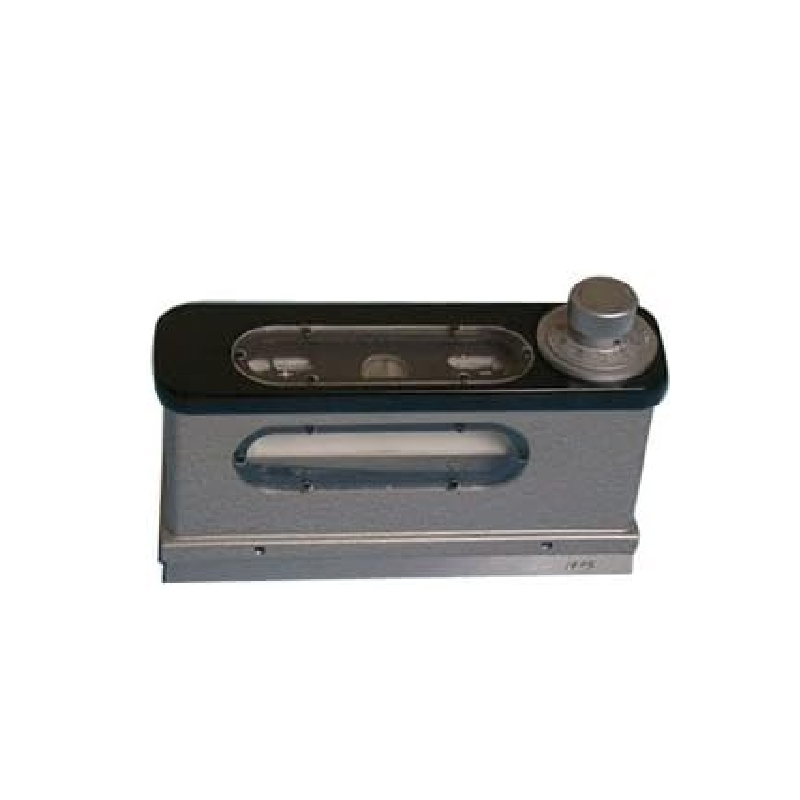

Optical Composite Image Level
The optical composite image level is used to measure the gradients of flat surfaces and cylindrical surfaces in the horizontal direction. It helps check the flatness and straightness of machine-tool slideways or bases, as well as the correct installation position of equipment.
Product Description
- 1. Application
The optical composite image level is widely used for measuring the gradients of flat surfaces and cylindrical surfaces in the horizontal direction. It can also be used to check the planeness and straightness of a slideway or the base of a machine tool or optical mechanical instrument, as well as to verify the correct installation position of equipment.
- 2. Technical Data
(1) Graduation value: ...0.01 mm/m
(2) Maximum measuring range: ...0 to 10 mm/m
(3) Allowance: ...1 mm within one meter; ...0.01 mm/m
Within the full measuring range: ...0.02 mm/m
(4) Plane deviation on the working surface: ...0.0003 mm/m
(5) Spirit level graduation value: ...0.1 mm/m
(6) Working surface (LW): ...165 × 48 mm
(7) Net weight of the instrument: ...2 kg
- 3. Structure of the Instrument
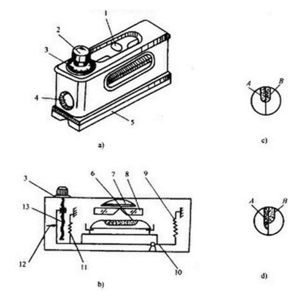
The composite image level mainly consists of a micro-adjusting screw, nut, graduated disc, spirit level, prism, magnifying glass, lever, and a base with flat and V working surfaces.
- 4. Working Principle
The composite image level uses a prism to form the air bubble images from the spirit level, and then magnifies them to improve reading accuracy. A lever and a micro-screw transmission system are used to enhance reading sensitivity. Therefore, when measuring a workpiece with a gradient of 0.01 mm/m, the reading can be obtained accurately with the composite image level (the spirit level in the composite image level mainly serves to indicate the zero position).
- 5. Operating Method
Place the composite image level on the working surface of the measuring workpiece. The measured gradient causes the two air bubble images to separate. Rotate the graduated disc until the two air bubble images coincide, and the reading can be obtained immediately. The actual gradient of the workpiece can be calculated using the following formula:
Actual gradient = Gradient value × Fulcrum distance × Disc reading
Example: Disc reading: 5 graduations. As this composite image level is fixed to the gradient value and fulcrum distance, the gradient value is 0.01 mm/m and the fulcrum distance is 165 mm.
So: Actual gradient = 165 × 5 × 0.01 / 1000 = 0.00825 mm
- 6. Operation Notices
(1) Before use, remove oil and dust with gasoline, then wipe clean using absorbent gauze.
(2) Temperature changes have a significant influence on the instrument. Therefore, keep the instrument away from heat sources to prevent measurement errors.
(3) During measurement, rotate the graduated disc until the two air bubble images completely coincide. Then take the readings in both the positive and negative directions.
(4) If the instrument is found to be out of the correct zero position, it can be adjusted. Place the instrument on a stable table and rotate the graduated disc until the two air bubble images coincide to obtain the first reading, a. Then rotate the instrument by 180° and return it to its original position. Rotate the graduated disc again until the two air bubble images coincide to obtain the second reading, b. The value 1/2 (α + β) is the instrument’s zero deviation. Loosen the three supporting screws on the graduated disc, press the embossed adjusting cap lightly by hand, and rotate the disc by 1/2 (α + β) to obtain the correct zero deviation and the coincident line composite. Finally, fasten the screws.
(5) After use, clean the instrument’s working surface and apply an acid-free, anhydrous anti-rust oil. Then wrap with anti-rust paper. Place the instrument in the wooden box and store it in a clean, dry location.
Hot Tags: Optical Composite Image Level Optical Composite Image Level suppliers China Optical Composite Image Level Optical Composite Image Level factory stable Optical Composite Image Level
Product Parameter
Technical parameters
- Plate value: 0.01 mm/m
- Measurement range: 0–10 mm/meter
- Parent–child error: within ± 1 mm/m + 0.01 mm/m
- Parental error over the entire measurement range: ± 0.02 mm/meter (reference value)
- Bench flatness deviation: 0.003 mm (reference value)
- Cell value accumulation standard: 0.1 mm/meter (reference value)
- Workbench size: 165 × 48 mm
- Net weight: 2.2 kg
Optical Composite Image Level Maintenance: Anti-Rust Oil & Storage Tips
Proper maintenance ensures your optical composite image level retains its 0.01 mm/m precision and durability. Follow these steps to protect its prism technology and mechanical components:
1. Daily Cleaning for Surface Protection
After use, wipe the working surfaces (V-groove, edges, lenses) with isopropyl alcohol on a lint-free cloth to remove oils and dust. Use a soft brush for stubborn debris—never use abrasives, which can scratch optical components or damage metal coatings. This helps preserve the precision-ground surfaces (Ra ≤ 0.1 μm) required for accurate readings.
2. Routine Anti-Rust Care for Metal Parts
While the granite base resists corrosion, metal components (screws, levers, hinges) require protection. Apply Storaen’s non-acid anti-rust oil every 3 months or after exposure to moisture:
Apply a thin layer to threads and pivots using a dropper, avoiding pooling on granite/lenses.
Helps prevent seizing: Maintains lever mechanism sensitivity (0.001 mm precision) for cylindrical slope measurements.
3. Optimal Storage Practices
Store the instrument in the included hard case or a dry cabinet to prevent temperature/humidity damage:
Environment: 10°C–30°C, <60% humidity to help prevent lens condensation and optical distortion.
Positioning: Store flat or upright in padded slots; never place heavy objects on the instrument to avoid misalignment of the optical system.
Long-term storage: Reapply anti-rust oil, add a silica packet, and inspect 24 hours before use. Verify the zero position using the 180° rotation calibration method.
4. Monthly Functional Inspections
Check performance regularly to ensure reliable operation:
Bubble clarity: Confirm that the composite bubble image aligns smoothly without blur.
Lever movement: Test the micro-screws for smooth rotation—excessive stiffness indicates the need for lubrication.
Flatness check: Use a reference plate to confirm factory-calibrated flatness (±0.0003 mm/m).
5. Storaen’s Support for Service Life
Leverage our expert services to maintain peak performance:
Factory recalibration: Restores 0.01 mm/m precision using ISO-certified equipment for critical applications.
Genuine parts: Replacement components ensure compatibility and help maintain original accuracy.
By following these steps, your Storaen optical composite image level will provide consistent precision for industrial alignment tasks, supported by our 30+ years of engineering expertise.
Zero Position Calibration of Optical Composite Image Level: 180° Rotation Method Explained
Accurate zero calibration is essential for your Storaen optical composite image level to maintain 0.01 mm/m precision and ±0.0003 mm/m flatness. The 180° rotation method eliminates subtle optical or mechanical shifts, ensuring dependable measurements in critical tasks such as CNC machine alignment or aerospace component inspection. Here is a streamlined, step-by-step procedure:
1. Why Calibrate?
Impacts, vibrations, or temperature fluctuations may shift the level’s zero reference, resulting in measurement drift. Calibration realigns the bubble vial with the tool’s optical prism and lever system, ensuring a consistent baseline for industrial applications where 0.001 mm deviations are unacceptable—such as verifying machine tool guides or structural frameworks.
2. Setup Requirements
Storaen optical composite image level (featuring a V-grooved base and micro-adjusting screw)
Certified precision reference flat (e.g., our Storaen granite surface plate, flatness ≤0.0002 mm/m)
A clean, vibration-free workbench in a temperature-stabilized environment (18°C–22°C recommended)
3. Step 1: Initial Measurement
Place the level lengthwise on the reference flat, aligning the V-grooved base with the flat’s central axis. Rotate the micro-adjusting screw until the composite bubble image (formed by the 45° prism system) perfectly overlaps in the viewing window. Record this initial scale reading (A), which reflects the current deviation from true zero.
4. Step 2: 180° Rotation & Second Reading
Carefully flip the level 180° end-to-end while maintaining its longitudinal orientation on the flat (avoid any lateral movement). Adjust the micro-screw again to align the bubble image and record the new reading (B). The difference Δ = |A - B| indicates the zero position error; ideal values for Storaen levels should be ≤0.005 mm/m.
5. Step 3: Error Correction & Verification
Calculate the target zero position as the midpoint: C = (A + B)/2. Loosen the protective cap on the zero-adjustment screw (typically located near the bubble vial), rotate the screw until the scale reads C, and then retighten. Repeat Steps 3–4 until Δ ≤0.002 mm/m, ensuring minimal residual error.
6. Pro Tips for Precision
Triple-Check Consistency: Perform 3 calibration cycles, especially after transporting the level or when working in environments with temperature fluctuations, to ensure repeatable results.
Lubricate Moving Parts: Apply a drop of Storaen’s non-acidic oil to the micro-screw before adjustment to ensure smooth operation without backlash and prevent sticking.
Environmental Control: Avoid calibrating near heat sources or in draughts, as even minor temperature gradients can affect the granite base’s dimensional stability and introduce errors.
7. Storaen’s Calibration Support
Each Storaen optical composite image level includes a NIST-traceable calibration certificate. However, quarterly in-field checks are recommended for heavy use. Our support includes:
Factory Recalibration: Restores the original 0.01 mm/m accuracy using laser interferometers for high-stakes applications.
Genuine Spare Parts: Adjustment screws and maintenance kits readily available for long-term usability.
Video Tutorials & Expert Guidance: Step-by-step videos and engineer support to assist with on-site calibration procedures.
Final Notes
Mastering the 180° rotation method ensures your Storaen optical composite image level delivers the precision required for cylindrical slope measurements, machine tool flatness checks, and other critical alignment tasks. With proper calibration, this tool—supported by our 30+ years of engineering expertise—becomes an indispensable asset in your quality control workflow, helping ensure every measurement is as reliable as the first.